The Worldtorch LDO Series Regulator Kit
This
kit of parts is intended to build a current regulator optimized for driving
one or more LEDs. Included is
an Integrated Circuit Current Regulator (Regulator IC) that controls a suitable
high gain transistor to supply the current for the LED load.
A low value resistor senses the actual current and this feedback signal
is sent to the Regulator IC where it is compared to an internal reference
to determine the drive for the transistor.
The circuit also uses two additional resistors and a capacitor for
stability and protection.
This
means that, within reason, setting the value of the sense resistor easily
controls the current. Included
in the kit are three possible resistors:
·
47
ohms (Yellow, Violet, Black, Gold) for 1.5 mA or so
·
10
ohms (Brown, Black, Black, Gold) for 6.5 mA or so
·
2.2
ohms (Red, Red, Gold, Gold) for 30 mA or so
Its
not necessary to use these values, of course.
You can calculate the value needed for any current by dividing 65 by
the desired current in mili Amps.
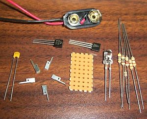
Also
in the kit you should have:
·
A small
piece of perf board
·
5 flea
clips (one is a spare)
·
LM334
Current regulator IC
·
2N3906
PNP Transistor
·
Two
390 ohm (O
·
A 1000
ohm (Brown, Black, Red, Gold) resistor (for use in 12 Volt systems)
·
A .1
micro Farad capacitor (looks like a match head)
·
A 9
Volt battery clip with wire leads
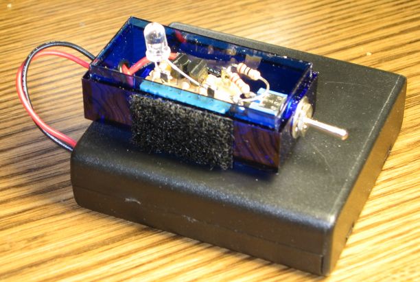
The
completed assembly is slightly smaller than half an inch wide, a bit less
than an inch long and under half an inch thick.
It connects with two wires from the battery and with two more to the
LED to be driven.
A
key feature is Low Drop Out, that is this is a true LDO series regulator.
In general its able to maintain proper regulation with a battery as
little as one tenth of a Volt higher than the necessary load (generally Vf
for the LED or LEDs used). This
means a close match of battery to load can give very high efficiencies indeed.
While
its assumed that most will want to preset a current (typically full blast),
its easy to make it adjustable. One
such scheme is to put a low value resistor in (say 47 ohms) to establish a
base current. Then use a switch
to add one or more resistors in parallel (connect the switch and resistor
network between the LED minus and
There
is a practical limit to raising the current.
Currents above 120 mA are not practical with this transistor.
Currents above that level raise the minimum Drop Out Voltage, cutting
into efficiency. Modified versions
can raise this limit within constraints of total power.
Indeed versions using a different transistor and a short length of
fine wire as a sense resistor have been used to drive one Watt Luxeon LEDs.
While the typical use is driving a single LED from a three or four cell battery (four to six Volts), other configurations are possible. For instance, driving three LEDs in series from a 12 Volt source is easily done. A 1000 ohm resistor is included for such uses, slight performance improvements can be had by using it rather than 390 ohms for the resistor between the transistor and regulator on the assembly. Not doing so (or using 1000 ohms in a lower voltage system) will not cause serious problems, but this simple substitution will optimize things a bit more, particularly at the end of battery life as it goes into direct drive. Within reason, shorts and reversed battery should not bother the circuit. Nor should connecting the LED backwards cause failure of either it or the regulator. Simply correcting the errors should get things going again.
Assembling
the Regulator Kit
To
make this assembly youll need a small pair of wire cutter to trim leads.
Small pliers or a small screwdriver or similar tool to help bending
leads is a help. However a good
job can be done with fingernails or other improvised tools as well.
Good cutters, preferably flush cutters are important.
In a pinch, fingernail clippers work fairly well at nipping off the
small soft leads involved. Solder
and a soldering iron will of course be needed.
Before
starting you might want to smooth any rough edges on the board with a file
or sandpaper, its much harder to do so after its assembled.
You can also trim the first row of holes off the board, making it .1
inches shorter, at the expense of some protection for the
This
assembly uses flea clips for inputs and outputs, although you need not do
so. Wires could simply be inserted
into those holes and soldered in place.
The clips just provide an easy way to modify and use the circuit after
its built. They are made of
thin Tin plated Copper. In practice,
they are inserted from the top through the holes.
Circuit connections to them are done on the bottom, leaving the top
slot free to accept wires when the assembly is put in service.
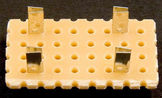
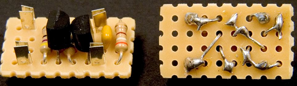
Begin
the assembly by holding the board horizontally so you have four rows of 8
holes each. From the upper left
corner, lets call these rows A, B, C, and D (top to bottom) and the holes
in each 1, 2, 3 and so on from left to right.
Insert
flea clips into holes A2, D2, A7 and D7.
In each case the flag on the clip should point to the left (the clip
in A2 should overhang A1 and so on).
An easy way to do this is to use the body of one of the resistors as
a tool. Drape the clip over the
resistor lead with the top of the flag up against the resistor body.
Pinch it and the resistor together and push the lead with the clip
around it down into the hole in the board (using the resistor lead as a guide).
Then pull the resistor lead out.
Spreading
the component leads a bit helps hold them in place until theyre soldered
in.
Next
insert the capacitor into holes B7 and C7 (between the two flea clips).
The
LM334 goes into holes B4, C4 and D4 with its flat side facing left.
This part should be inserted (spreading the leads) in to the board
until its just above the resistor under it, say 1/8 inch above the board level.
The 2N3906 goes into holes B6, B7, and B8 facing right (this means
the two transistor package parts are back to back).
They have their round sides touching, flat sides (with the printed
labels) facing out, again insert the part to about 1/8 inch.
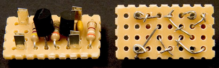
Now
flip the board over so the rows of holes are now D, C, B, and A top to bottom,
but the columns are still 1 to 8 left to right and make the following interconnections:
·
D2,
D3, and D4 connect together. Bend
the transistor lead at D4 down against the board, past D3 on the C3 side,
and wrap it around the flea clip at D2.
Then bend the resistor lead at D3 down tight over it (straight down
toward C3). Trim the two leads
and solder in place at D2 and D3.
·
D6
and D7 connect together. Bend
the transistor lead at D6 flat to the board then wrap it around the flea clip
at D7, cut to length and solder down at D7.
·
D8
and C7 connect together. Bend
the transistor lead at C7 flat and then up and around the base of the resistor
lead at D8. Be sure to put a
kink in the lead to keep it away from the flea clip at D7.
Fold the resistor lead down over the transistor lead as close to D8
as possible, cut both to length and solder at D8.
·
A2,
A3 and C4 connect together. Bend
the transistor lead at C4 flat then down and around the base of the resistor
at A3 (again put a kink in it to avoid the B4 area).
Bend the resistor lead at A3 down flat then loop it around the flea
clip at A2. Trim both leads and
solder down.
·
B4
and A5 connect together. Bend
the two leads toward each other, trim them off at the other hole, bend one
or the other down tight over its mate and solder down.
·
D5,
C6, and B7 connect together. This
ones tricky. Bend the capacitor
lead at B7 down, run it past the transistor lead at C6 and around the base
of the resistor lead at D5. Now
bend the transistor lead at C6 down over the capacitor lead tightly.
Trim both leads, inspect carefully for clearance around B6 and D6,
and solder down at C6 and D5.
·
B6,
A7, and A8 connect together. Bend
the resistor lead at A8 flat, then around the flea clip at A7 and up next
to B6 on the A6 side. Fold
the transistor lead at B6 snugly over the resistor lead, trim both and solder
down at B6 and A7.
In
each case, the leads involved should be bent to make contact, cut to length
and soldered together. Be sure
to check for shorts where the leads are close together like at B4, C6, A7,
D7 and similar tight spots. Try
to keep things tight to the board.
The
assembly connects as follows:
LED
plus (long lead) to clip at A7
LED
minus (short lead, flat) to clip at A2
Included
in the kit should be a 9 volt battery snap connector with wire leads.
Soldering it to the top end of the
Once
youre satisfied that everything is working OK, you might consider a coat
or two of clear fingernail polish to protect the back side of the board from
shorts, moisture and the like in later life.
Double stick foam tape is often a good way to mount small assemblies
like this. A coat or two on the
top side, right over the parts and wires, will complete the protection (should
you decide you need to).