Boost Circuit Kit Run an LED off of a single battery!
|
 |
Using the completed board
The completed board may be driven by voltages between .8 and 3 Volts. While the basic design goal was ‘candle like light from a single cell’, the values used were chosen to allow safe operation from 3 Volts so you can, for example, use it to ‘drain the last bit of energy’ out of used Lithium based cells from flashlights. This means that you can also drive it from a fresh 123 cell at full brightness (for 16 hours or so) or two NiMH, alkaline or other cells in series. While the current consumption (and therefore light output) goes down with supply voltage, some light is produced even with very low inputs.
Payment (Only $5.00 and that includes shipping):
1. Trim the board to the final size you want before assembly.
The board may be sawn, sanded or filed to shape. It is designed to be round
should you want, a bit less than the diameter of an AA cell (will fit inside
common plastic pipe).
2. Hold the board so that the square pads for the battery connection are on
the right, with plus above minus as shown above.
3. Install the 470 uH inductor (looks like a resistor) next to the input pads,
spread the leads on the back side to hold it in place until soldered. No polarity
concerns.
4. Install the two transistors as shown, watch the flats as they determine
polarity. Spread the leads again to retain the parts until soldered.
5. Install one of the 1 K resistors (Brown, black, red, gold) and the .001uF
cap (looks like a match head) above the LED mounting area as shown, again
no polarity concerns.
6. The other 1 K resistor goes next to the LED on the left side, the 2.2 K
(red, red, red, gold) outside that on the edge as shown, again spreading the
leads on the back side.
7. Solder all components in on the back side, trim the leads.
8. Install the LED. It can be put through either side and mounted flush to
the board or elevated to provide a number of options. Just be sure to watch
the polarity, the longer lead goes to the round pad, the positive (shorter
lead, with the flat on the rim) goes in the square pad no matter how the LED
is mounted. Solder and trim the leads.
9. Connect the power leads to the square pads. The leads can be brought in
from either side. Solder and trim as necessary.
Some fun things to try with this circuit:
1) Take a "dead" battery from one of your electronic devices (say a digital camera, walkman, etc.) and hook it up to this circuit and see how long you get light.
2) Take two really "dead" batteries and hook them up in series to this circuit... if you don't get any light from the LED then you have successfully sucked out all the life from those batteries!
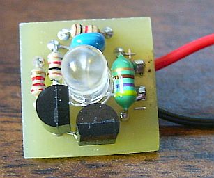
Boost
Circuit Front
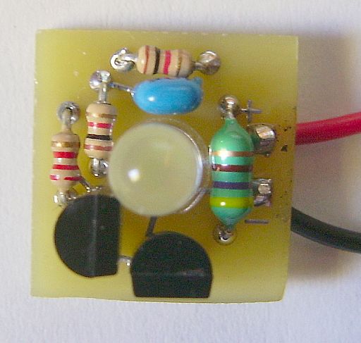
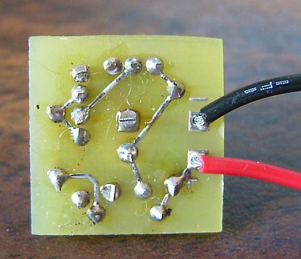
Boost
Circuit Back
(flipped top to bottom)
Boost Circuit Schematics
Below is the current schematic for the Boost converter. The negative power is connected to the emitters and LED cathode. With the values shown, the circuit draws about 18 mA and drives the LED to 5 mA or so. Higher input voltage, up to 3 volts assuming white LED use, pulls more current and therefore produces more light. Changes in values will change performance. Attention should be paid to the inductor, as it is the key in most cases. It needs to be capable of dealing with peak currents and not saturating.