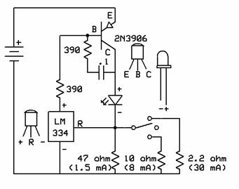
This is the schematic for the Low Drop Out (LDO) regulator circuit based on the LM334. The transistor boosts the available current (limited to 10 mA by the IC) to higher levels needed to drive the LED. In the example above the 47 ohm resistor (which is always in circuit) sets a basic current of about 1.5 mA. When the switch is not in the center position (open circuit) either the 10 ohm or 2.2 ohm resistor is put in parallel with it, raising the total current. This gives low, medium and high levels, each regulated.
In each case, the regulator (the LM334) compares the
voltage between it’s R and minus leads (caused by the voltage drop in the
resistor(s) as a result of the actual LED current at that point in time) against
an internal reference of approximately .065 Volts. It then drives the transistor more or less to
correct the LED current to match the preset value. Thus LED current stays constant for changes
in battery or LED voltage.
This
circuit will hold the LED current constant as long as the battery is voltage
is high enough. In this case, with
the parts and values shown above, this required minimum voltage is under .1
Volt more than the forward voltage (Vf) of the LED at the current in use. This means that since at lower currents Vf is
less (and the battery is likely loaded less, producing higher terminal voltage,
the circuit will stay in regulation “longer” (into the useful life of the
battery). That is when the circuit
and battery in question will no longer regulate at 30 mA (high), it will still
do so at 8 or 1.5 mA (medium or low).
In
practice the 390 ohm resistor and .1 microfarad capacitor from base to collector
can come in either order (that is they can be reversed).
With
these values, the circuit current can be raised to a bit over 100 mA (for
example to drive 4 LEDs in parallel). Higher
currents call for a different transistor and perhaps different values of the
related parts.
The
basic circuit can also be used to drive several LEDs in series, provided the
battery voltage is raised. For instance,
3 white LEDs are well driven from 12 Volts.
Close
match between battery voltage and Vf can yield very high efficiencies indeed.
For instance 3 NiMH cells (nominal voltage a bit over 1.2 each) can
drive a typical white LED (typical Vf of 3.2 to 3.6 depending on current)
with well over 90% efficiency. The naturally flat discharge voltage of these
cells will keep the circuit in regulation (at very high efficiency) until
the very end of the useful charge. Use
of alkaline cells (with their constantly dropping voltage) calls for four
cells typically (for full usage) or “leaving useful energy behind” with 3
(although the efficiency will be higher), making the “3 or 4 cell” decision
a compromise.