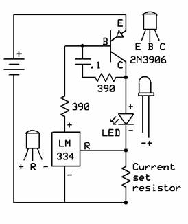
This is the schematic for the Low Drop Out
(LDO) regulator circuit based on the LM334.
The transistor boosts the available current (limited to 10 mA by the
IC) to higher levels needed to drive the LED. The regulator (the LM334) compares
the voltage between it’s R and minus leads (caused
by the voltage drop across the current set resistor as a result of the actual
LED current at that point in time) against an internal reference of approximately
.065 Volts. It then drives the transistor
more or less to correct the LED current to match the preset value.
Thus LED current stays constant for changes in battery or LED voltage.
The value (in ohms) needed for any given current is .065 divided by
that current (in Amps).
This
circuit will hold the LED current constant as long as the battery is voltage
is high enough. In this case, with
the parts and values shown above, this required minimum voltage is under .1
Volt more than the forward voltage (Vf) of the LED at the current
in use.
In
practice the 390 ohm resistor and .1 microfarad capacitor from base to collector
can come in either order (that is they can be reversed).
With
these values, the circuit current can be raised to a bit over 100 mA (for
example to drive 4 LEDs in parallel). Higher
currents call for a different transistor and perhaps different values of the
related parts.
The
basic circuit can also be used to drive several LEDs in series, provided the
battery voltage is raised. For instance,
3 white LEDs are well driven from 12 Volts.
This could also feature 3 or 4 such “strings” of LEDs in parallel for
even more light output (with lower sense resistor). It’s important to keep the current in any given
LED in the safe range of course.